Engineering Explained: How Viscous Limited-Slip Differentials Work
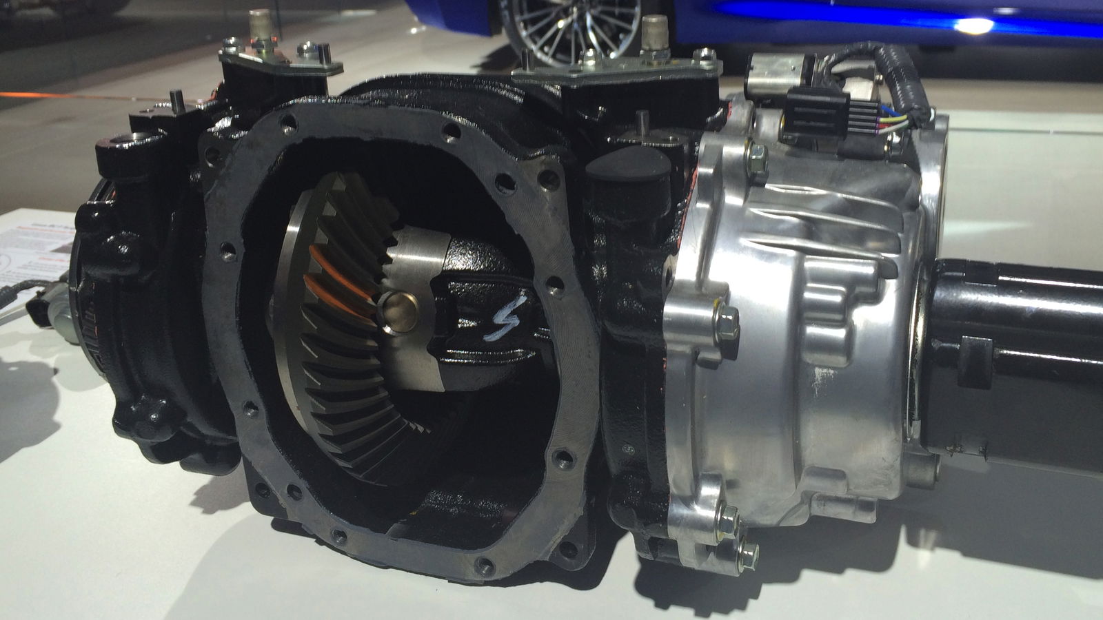
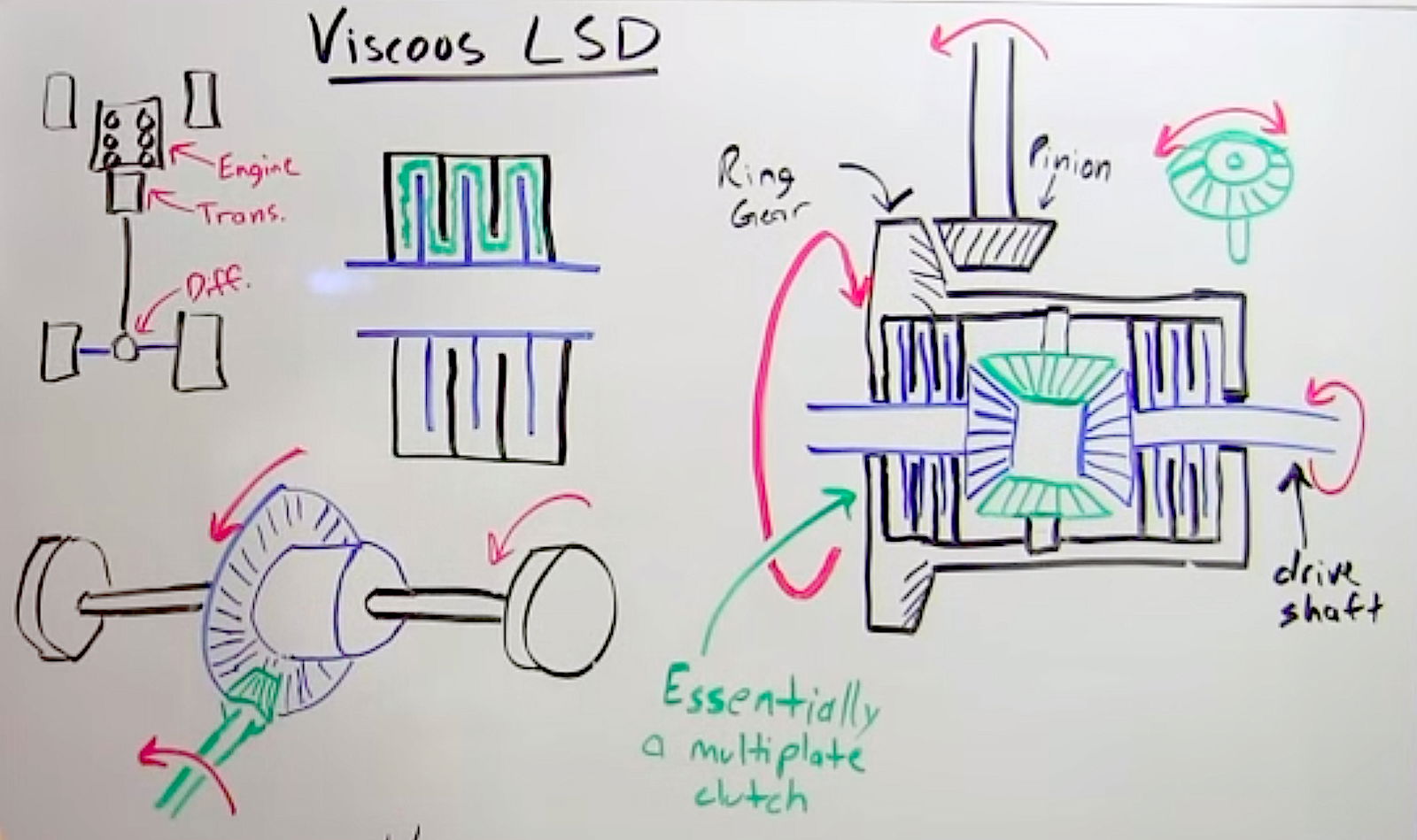
There’s a bit of terminology to know (see illustration below) before understanding how viscous limited-slip differentials work. As is generally the case, many of the terms have alternative names; I’ve simply chosen terms that are commonly used and simple to understand.
Pinion
The pinion rotates the ring gear and is connected (directly or indirectly) to the transmission output, thus it supplies torque to the differential.
Ring Gear
The ring gear is meshed to the pinion, thus it rotates the differential housing. It is concentric with the output shafts and the drive gears.
Viscous Coupling
The viscous coupling is very similar to a multi-plate clutch, where there are alternating friction discs and plates which can rotate separately. The friction discs will be splined to one of the output shafts (or both, as shown below - though it is more common for a single coupling). The plates between the friction discs will rotate with the differential housing, thus the two components have the ability to rotate separately. This coupling is housed in a viscous fluid (oil) which is where the name is derived.
Side/Drive Gear
These gears are on the ends of the drive shafts (seen in blue below) and are what the spider gears mesh to, thus transferring torque from the rotation of the differential to the driven wheels.
Drive/Axle Shaft
These connect with the drive gears, and are the output shafts of the differential, sending torque to the driven wheels.
Spider Gear
The spider gears (seen in green below) mesh with the drive gears, however they rotate with the differential housing. They are on bearings around the pinion shaft, which allows them to freely rotate about the axis of the pinion shaft.
Pinion Shaft
The pinion shaft (split into two separate shafts below) is what holds the spider gears in place. This shaft is connected with the differential housing, thus the spider gears rotate with the housing.
Differential Case/Housing
The housing holds the coupling, axle drive gears, pinion shaft, and spider gears inside of it. It rotates with the ring gear.
To understand how it works, first let’s look at the order in which torque is transferred.
1. Torque is sent to the transmission output shaft, where it then transfers from the pinion to the ring gear.
2. The ring gear rotates the differential housing, sending torque through the pinion shaft.
3. The pinion shaft rotates the spider gears, transferring torque from the pinion shaft to the drive gears.
4. The torque is sent from the drive gears through the axle shafts to the driven wheels.
Onto the viscous coupling, and how it works. It’s easiest to understand this by looking at a scenario when one of the driven wheels has limited traction (let’s imagine it’s on ice) while the other driven wheel has plenty of traction (on pavement). With an open differential, torque is evenly split between the two wheels (50/50). Since a wheel on ice can’t supply much torque, the other wheel will have limited torque as well, and often the vehicle will not be able to accelerate (this is why locked differentials are so prevalent for off-road vehicles). With an LSD, you are able to transfer more of the torque to the wheel with more traction.
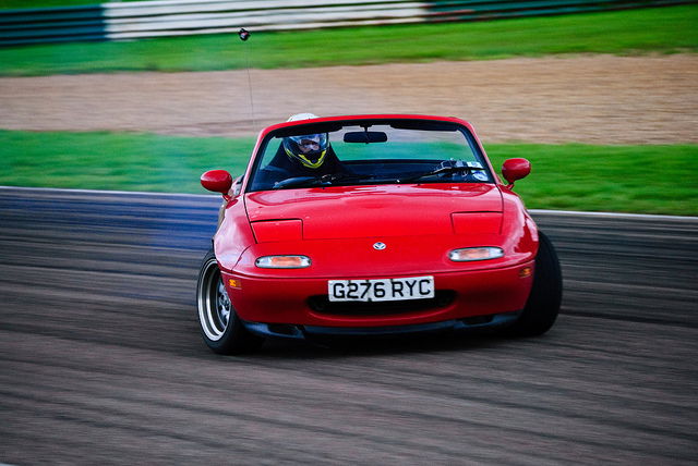
Here’s how it works:
1. With one driven wheel on ice (let’s say the right wheel), and one on pavement, the wheel on ice will begin to slip (spin) as you apply the throttle.
2. Since the wheel on pavement has more traction, it will not spin.
3. As the wheel on ice begins spinning, the differential housing (and thus the plates of the viscous coupling) will begin to rotate, while the friction discs connected to the left output shaft remain stationary (or at a lower rate of rotation).
4. When this occurs, the fluid within the coupling begins to heat up and rotate with the differential housing. Friction between this fluid and the stationary/slower-moving friction discs forces the friction discs to rotate at a faster rate.
5. By bringing the rotational speed of the left output shaft closer to the right output shaft, the differential acts more like a locked differential, and thus more torque will be sent to the wheel with more traction.
6. This is beneficial in any scenario where tyre slip starts to occur, thus decreasing the total amount of torque which can be put to the ground.
Here’s a four-minute video on how they work:
Check out more articles from Engineering Explained.


Comments